Table of contents
Control Voltage - CV
How Daisy can send or receive CV signals over some of it’s pins.
👀 This page is still in draft mode.
Example for the json file: https://github.com/electro-smith/json2daisy/blob/main/src/json2daisy/resources/patch_init.json
You can send values between 0 and 1 to those send objects.
[s cvout1 @hv_param]
you need regular control messages
the cv i/o in Daisy are all running at control rate. so they evaluate once every audio block (every 1ms at default settings)
From Daisy forum, an answer by Takumi Ogata:
Name
Control Voltage - CV
CV/gate (an abbreviation of control voltage/gate) is an analog method of controlling synthesizers, drum machines, and similar equipment with external sequencers. The control voltage typically controls pitch and the gate signal controls note on-off.
The Daisy Seed outputs 0.0V-3.3V out of its DAC outputs. And on boards like the Daisy Patch, that signal is amplified to 0.0V-5.0V.
function - what can it do
Unlike the midi format, CV is a protocol of communicating with variable Voltages. It is an analog way of sending or receiving a value.
It is often used on desktop synths to allow communicating with other synths or Eurorack systems.
what it looks like
Generally CV is transferred via a TS, mono patch cable, in the 3.5mm jack format.
Pins
Eurorack and CV signals vary in the range they operate in, on some devices you can setup what this range is. Typical ranges are –5V to 5V, 0V to 5V, 0V to 10V …
The Daisy Seed outputs 0.0V-3.3V out of its DAC outputs. And on boards like the Daisy Patch, that signal is amplified to 0.0V-5.0V.
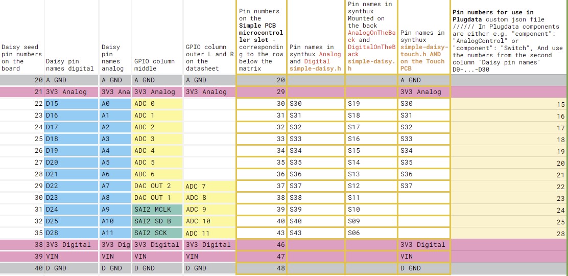
[…] So pin D20 can be analog input or even digital output. Also worth noting that, even if you decided to use pin D20 as analog A5, it doesn’t care if you’re using an analog component like potentiometer or digital component like a switch as long as the voltage coming in is 0.0V to 3.3V range.
ADC: all Analog labeled pins: D15 to D25 and D28 DAC OUT: Only pins D22 and D23
If you need more in/out-puts you’ll need to add some extra circuitry: e.g. for arduino / cpp Takumi Ogata posted this: Let’s Add 4+ More DACs/CVs with Quad DAC! (Also, I2C tips!)
GPIO overview table of the analog ADC DAC pins:
Components json
This json is set up for a Synthux Simple Fix pcb. There are two pots and two mono jacks installed on this board. Note how cv_1 is also setup like a potentiometer with "component": "AnalogControl"
{
   "name": "SimpleFix",
   "som": "seed",
   "audio": {
     "channels": 2
   },

    "components": {
       "knob0": {
           "component": "AnalogControl",
           "pin": 15
       },
       "knob1": {
           "component": "AnalogControl",
           "pin": 16
       },
       "cv_1": {
           "component": "AnalogControl",
           "pin": 17
       },
       "gate_in_1": {
        "component": "GateIn",
        "pin": 18
       }

   }

}
Download this file simple-fix_2knobs_1cv_1gate_in.json
Example for the json file for the Electrosmith patch.Init():
https://github.com/electro-smith/json2daisy/blob/main/src/json2daisy/resources/patch_init.json
PD example(s)
…
links / references / sources
PD to C with plugdata - Custom Modular Synth Voice - video by Wasted Audio:
- https://www.youtube.com/watch?v=NZ8c3VkBXRQ
Example for patch.Init() on the json2daisy github repository: json file for Patch Init
- link to this Eurorack module: https://electro-smith.com/products/patch-init
Daisy forum, an answer by Takumi Ogata
For arduino / cpp Takumi Ogata posted this: Let’s Add 4+ More DACs/CVs with Quad DAC! (Also, I2C tips!)